
Today i bought a BLDC hub motor! Why? I don’t know really. Well of course I know why, but I haven’t got an application for it.
I want to learn how to control it. I want to use cool PIC microcontrollers that I recently have started to program again. And I want to fiddle with optimization on driving it with torque and power saving. But do I need it? Silly question, all we actually need is to choose and to die! 
The motor was cheap. But it didn’t come with any documentation what so ever. So my idea is to post information about it, and my progress with it, as i proceed.
Here are some data I have collected:
On the outside it is marked with 24V26C JS08030167
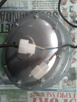
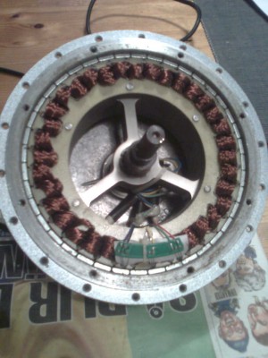
And when i took it apart:
3 poles, 36 teeth
40 magnets
3 hall effect sensors
2 ball bearings
3 thicker wires to the windings
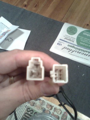
5 thinner wires to the sensors (two for power and three for outputs from the sensors)
The hall effect sensors are three pin and connected like this:
Red +
Black GND
Green output from sensor one
Yellow output from sensor two
Blue output from sensor three
I added 5volt over the red and black wires and measured volts at the outputs while i slowly rotated the motor with my hand. I made a quick table over the values I got, it looks like this: As we can see, one is always off. But i’ll have to read more about hall effect switches to know exactly what that means.
I read some more about different hall effect sensors and it seamed that the most common one (and the cheapest… a good way of finding out what is inside consumer products) is to be treated as a transistor witch sourches about 25mA. So I decided to drive som LED’s. Here is the movie:

Rename the file to whateveryouwant.3pg. It is a bad quality phone video, but it will show the rythm om the sensors quite well. When I reverse the rotation of the motor the sequence of the LED’s simply reverse too.
The overall quality of the motor is varying. Mecanically it is well made, but when it comes to the wireing and hall sensors it lacks bigtime. Even the thread is very poorly made and one of the bolts was broken on delivery. Like other chineese stuff I have seen it is a strange combination of high ambitions and unnessecery poor workmanship.
Here are some pictures:
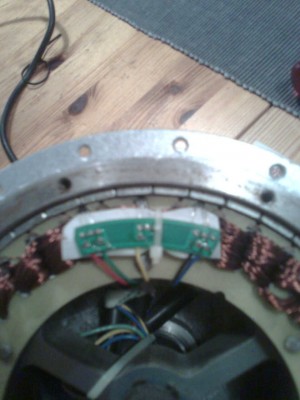

As you can see there is som kind of marking inside the motor. I dont understand chineese. If somebody can read the markings, please let me know what it says.
Somehow I believe that theese markings is the factory name. Maybe this can help me in finding some documentation.
I think I have found my favourite way of driving the motor. I have been heavily inspired from http://www.ltu.se/polopoly_fs/1.35847!elektronikrapport.pdf and the BALDOS project at LTU. By reading their description and looking at their designs I finally found the missing link between the RC hobby motors and the more heavy duty hub motor.
I also finally found enough courage to energize the motor windings. I am by no means good att power electronics and I dont want my hub motor to end up in flames. I have been studying different ways of limiting the current to the windings to prevent melting while elaborating. I ended up using thin copperwire so that this thinner wire would melt long before the motor took any damage. I now know that the motor move when using only 12V. That makes things a lot easier to elaborate with since I can use a car battery.
I have decided to make the driver electronics in modules. That enables me to change some of the modules without starting all over again, should I regret any of the designs. I have settled on the following modules:
* CPU module, containing microcontroller and surrounding electronics.
* Sensor module, it will be nothing right now, when I use the hall sensors, but who knows, maybe I’ll try a sensorless design later.
* Driver module, containing the power electronics like the mosfet’s and their drivers.
* MMI module, the interface to us humans. Maybe a gas handle or a laptop application.
* Charger module, for battery charging. From 220 and regenerative from braking.
In practics I already have the CPU module. Several of them! Sensor module is not needed right now when sensors can be attached directly to the microcontroller. So the first module to build will be the driver module.
I think I finally found a good design for a driver module. My Idea is to have the IC IR2130 as a driver circuit. It contains some safety functions that could come in handy.
As the power-hexfet I think i will use IRFP460. It is one of the hexfets that is powerful enough yet almost affordable.
Each phase will be driven by a circuit like this:

 I mounted the chassis on distances so that the cooling outlet from the monitor would not be blocked. I drilled holes for standard motherboard mounting distances and mounted the motherboard as in any normal computer case. I then glued plastic “rails” made from a CD case on the power supply and pushed the rails in the AGP and PCI slot connectors. Making the power supply “piggy backed” on the motherboard.
 The CF-card and the IDE adapter is located under the ribbon cable. And as you can see there is plenty of room between the power supply and the MB for cooling.
 Here it is, all hooked up and “ignited”. I used double CPU coolers to get enough passive cooling. The slimline case i had made also have a perforated cover that I have removed to take the photos. With the cover on, it looks almost as a commercial product. Well… a little bulkier.
 The monitor have built in speakers that sound far better that my old clock radio and the KDE desktop is configured to be “fool proof”. Only a handful icons are used. One for gmplayer, one for juk and one for the KDE settings panel. If it is possible, the mouse pad is just temporary.
 A numpad keyboard is used to make the remote control. I bought a cheap but good looking numpad and modified it with “the brain” of an old wireless keyboard. Then I remapped some of the keys in X so that i get the functions i want on board the numpad. The TAB key and the SPACE key for example. Here is a picture from the inside of the numpad.
 The gutted numpad leaves just enough room for the wireless transmitter and a 3 volt battery. The transmitter is the same model as my (tucked away) wireless keyboard. So I can “sync in” a normal keyboard for maintainance.
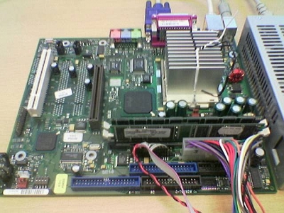

 or this
 scheme from